Every parts manufacturer looks at reducing costs while seeking to retain a repeatable and accurate process to produce components that require a tight tolerance. Machining using CNC (computer numerical control) technology is often the best solution for high-volume part production. With CNC machining, speed combines with accuracy to support the fabrication of precision components.
The advantages of tight tolerance machining for mass production of parts and products are obvious, and the use of modern CNC technology supports this. Tight tolerances improve part or product performance, leading to more consistent quality, fewer failures, and improved durability and strength. As today’s CNC machines produce less waste and reduce fabrication times, they also improve operational efficiency over time. But the main goal tight tolerance machining seeks to achieve is superior product performance.
Efficient Production with Tight Tolerance Machining
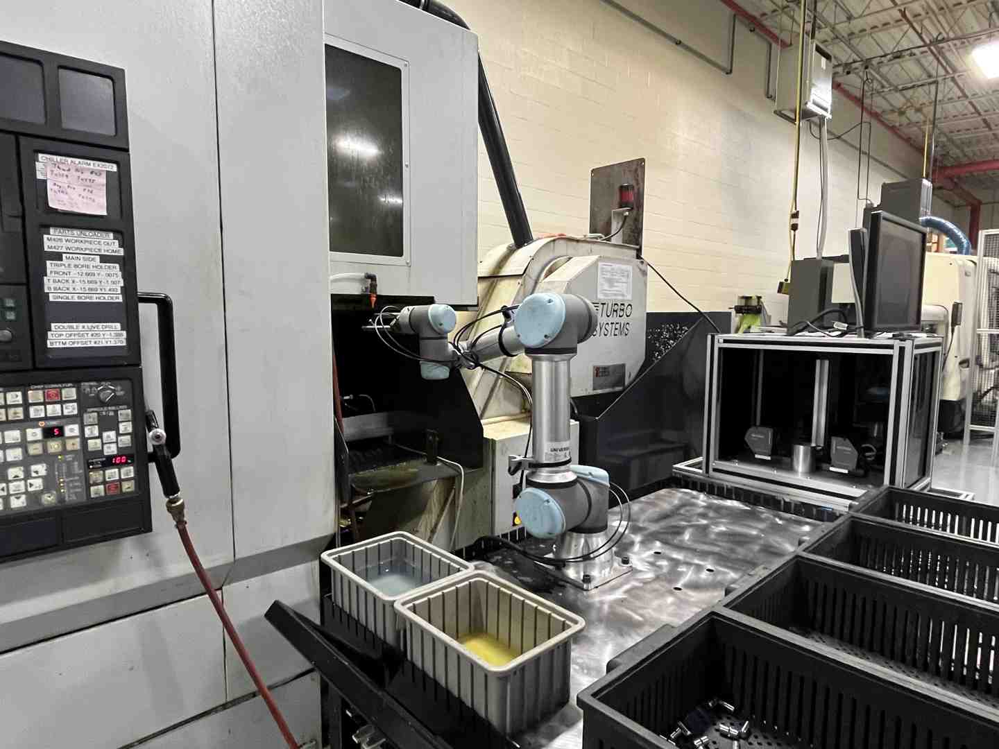
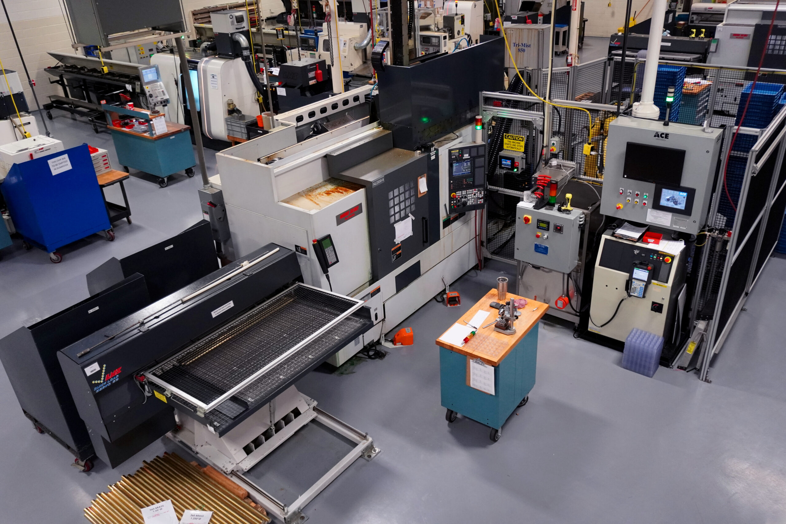
Machining methods have become increasingly automated to achieve a tight tolerance, with CNC machines programmed to produce exacting specifications at high speeds. To attain top-quality work, shops require milling machines and lathes to carve a workpiece horizontally or vertically at high speeds from many angles. Robotic arms and other automation are also features in modern machine shops, controlling every motion of a CNC machine and cutting workpieces along multiple axes.
Tight tolerance machining starts in the design stage, helping to ensure newly designed products work as they should in real-world situations. Design for Manufacture and Assembly (DFMA) helps streamline this design process, allowing manufacturers to create digital models. This helps support the fabrication of parts with a tighter tolerance, the machining of which involves computer-aided design (CAD) software.
It All Starts with Design
A digital CAD model is the first step in ensuring a design will work and that the fabrication processes are sound. Once the digitized model is complete, it’s transferred onto computer-aided manufacturing (CAM) software, which creates the instructions that allow CNC machines to produce the part. These instructions can later be used to produce identical components from manufacturing blanks.
Typically, CAM software instructs the CNC machine to:
- Turn the manufacturing blank, including how rapidly and in which direction.
- Have tools follow certain programmed paths to create the part’s final geometry.
- Direct how quickly and where the machine’s tools cut.
- Determine precisely how it moves and to which locations.
- Cut away material from the workpiece at a certain speed.
- Move within a specific number of axes using a three- or five-axis coordinating system.
A three-axis CNC machine’s computerized controls guide the cutting and other movements simultaneously on X, Y and Z axes. Five-axis machines utilize the typical X, Y, and Z-axes in conjunction with the A and B-axes.
The Best Cutting Tools for Tight Tolerance Machining
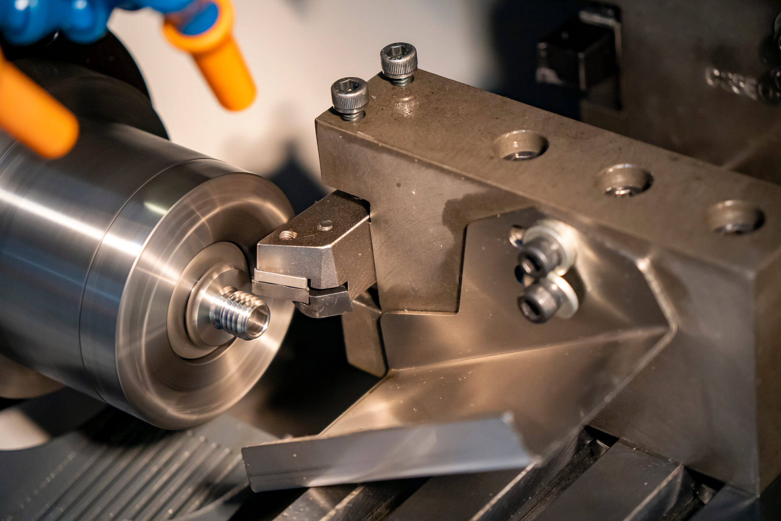
Two main categories of CNC machines utilize cutting tools, each working distinctively to achieve differing results. CNC lathes, for example, rotate the workpiece as a fixed cutting tool removes material. Conversely, CNC mills keep the workpiece stationary while the tool rotates around it.
CNC lathes generate better outcomes for cylindrical workpieces, allowing for more complex movements. For square or edged features, CNC mills work better. A CNC lathe creates the rounded geometry for cylindric workpieces with square features before a CNC mill cuts the areas with straight edges.
Component size is limited by a milling machine’s tool clearance and how deeply it can cut. When it comes to a lathe, this depends more on how much area is available for fabrication. Sometimes, a live tooling lathe can be used instead, which combines the capabilities of both the CNC mill and the CNC lathe. These machines are useful solutions for parts with complex features, as they reduce lead times.
Understanding the Difference Between Default & Tight Tolerance Machining
Normally, it’s the customer who provides part specifications, including how tight the tolerance. Machining components usually allow for metal parts that are 0.005 inches (0.127 mm), larger or smaller. Walls for metal components must be a thickness of 0.030 inches (0.762 mm) at a minimum.
Finishes are milled to an even tighter tolerance. A CNC milling machine does machining surface finishes, though these treatments are only applied when customers request them. Generally, maximum surface finishes are equivalent to 125 microinches (3.175 μm). Finishes are based on the root-mean-square (RMS) of all the part’s peaks and valleys.
Very Tight Tolerance Machining
Sometimes, a component needs to be made with a very tight tolerance. Machining to these specifications adds expense as it often increases waste, requires more machine reconfigurations, takes more time for measuring, or a combination of any or all of these three. The length between cycle times often slows down the machining process, adding to the cost, so tight tolerance machining should only be applied when specifications require it.
Choosing the Materials & Size of Manufacturing Blanks
Along with the size of the blank, the choice of raw material used will affect the cost of a workpiece. Plastics tend to be considerably less costly, though metal is normally preferable when rigidity is a factor. However, certain softer metals like aluminum and brass are easier to machine than carbon, stainless and other steels.
Often, material selection for a component depends on cost, though its design and use will also limit this aspect of the manufacturing process. The application will often determine whether properties like chemical resistance, hardness, rigidity, and thermal stability will be necessary. These materials come to the machine shop as manufacturing blanks.
Generally, 0.125 inches (3.175 mm) over the part’s designed measurement should be added to the blank’s depth, length, and width to remove the material.
Choosing the Right Equipment for Tight Tolerance Machining
Part manufacturers requiring tight tolerance machining generally choose between production on 3-axis or 5-axis CNC milling machines. The fewer axes that need to be worked, the easier it is to cut and the lower the cost. As such, cutting on two axes is the easiest and least expensive, and it can be done on either type of CNC machine. Contoured components that move the cutting tool simultaneously along the X, Y, and Z axes—also referred to as 3-axis cutting—are more expensive to manufacture.
More complex parts require a 5-axis CNC machine to be made cost-effectively. With 5-axis machining, both the tool and manufacturing blank can move along five axes, decreasing the number of setups necessary. This allows quicker cutting speeds, more accurate tool paths, and better surface finishes. When applied to tight tolerance machining, 5-axis CNC machines can produce complex components with greater accuracy and speed, often making their use more economical for these projects.
Component Geometry & Tight Tolerance Machining
Several features can benefit from tight tolerance machining. Four of these are fillets, undercuts, threading, and surface finishes.
Fillets
Rounded corners on the exterior or interior of components are known as fillets, designed into a part’s geometry using CAD software. When they occur on interior corners, they’re concave. When they occur on the exterior, fillets are convex and often described as “rounds.” Normally, fillets are designed for joints that have been brazed, soldered, or welded.
Whether working on a vertical or horizontal axis, a CNC milling machine uses a radius cutting tool to achieve a tight tolerance. Machining with this roundish tool shapes a component’s inside walls on the vertical axis, spinning quickly and removing material from the blank to produce the grooved features in the design. However, there are limits to where these convex or concave features can be made.
Non-standard radius cutters make inside corner fillets more easily, though mills require sufficient clearance when turning to keep milling. Adding 0.02 inches (0.508 mm) to internal radii allows the cutter to turn only slightly while it continues cutting. Using non-standard cutters can cut costs and result in superior machined components.
Generally, producing a part with a larger radius is less costly. Making fillets on a component’s floor is easier. However, if the wall’s and floor’s radii are identical in size, removing corner material becomes more difficult. When the floor’s radius is smaller than the wall’s, the same cutting tool can be used throughout the cutting process.
Undercuts
Due to their inaccessibility with straight tools, undercuts can be especially challenging to machine to a tight tolerance. Undercuts refer specifically to a sunken surface on a part, though they’re described differently depending on whether CNC milling or turning is used for fabrication. When milling to a tight tolerance, machining undercuts denote a feature not visible from the spindle. In turning processes, undercuts are usually on the component’s inside diameter.
For an undercut with a tight tolerance, machining must often be done with a special tool if a standard tool can’t reach it, which results in this undercut feature. Normally, standard dimensions are used as creating custom tooling raises the expense by at least double if not more. However, ensuring undercuts aren’t too deep and are reachable by a machine’s tooling is essential, though undercuts must also be made deep enough.
Threading
Creating a hole into which a screw can fit is what’s known as threading, a process for which it’s particularly difficult to achieve a tight tolerance. Machining screw threads involves cutting and grinding with a rotating cutter tool on a CNC mill that follows a helical toolpath. Machining should include evacuating the chips coming off the blank when achieving a tight tolerance.
If these chips aren’t removed before the threading process, it could interfere with the tool’s tip, leading to unwanted vibration. This disrupts the thread’s continuity while shifting the points where a screw would make contact. Discontinuity in the thread can mean a failing grade during a quality check on the component. Since threading generally occurs as one of the last processes, removing chips from the hole decreases the chance of damaging the hole.
While some applications require a tight tolerance, machining standard thread sizes reduces costs. Parts should also be machined to the largest thread possible, as more diminutive tapping tools are more likely to break than larger ones, adding to the expense. Threaded holes should also only be made as deep as needed, as the deeper the hole, the more costly it will be. However, machining with custom tools may be necessary, with parts requiring a deeper hole with a tight tolerance.
Surface Finishes
As alluded to earlier, standard mill finishes are 125 RMS, which can leave minimal markings from tools still visible. However, it’s possible to attain a tighter tolerance for machining finishes as thin as 16 RMS. These smoother finishes increase the time it takes to fabricate a component and add to the expense. Many finishes can be used when manufacturing parts to a tight tolerance. Machining precision parts also involves finishing processes like anodizing, bead-blasting, grinding, or powder-coating that add useful properties to the finished component.
The basics of each of these surface finishing processes:
- Anodizing: Used for aluminum and other non-ferrous metals, this electrochemical process provides metal surfaces with an aesthetic finish that’s both durable and resistant to corrosion; it allows for variously colored or even transparent finishes, while harder anodization can provide a thicker layer on the surface to offer greater wear-resistance.
- Bead-blasting: As a type of abrasive blasting, instead of using irregularly shaped media that leaves a coarse finish, bead-blasting uses spherical glass media that leaves a uniform, dimpled surface; though more expensive, areas can be covered so that the matte finish resulting from the process only occurs where desired.
- Grinding: CNC technology can grind a part’s surface with an abrasive grinding wheel to provide the part with an extremely tight tolerance; machining may involve first turning the component, after which centered or centerless grinding is used to complete the finish.
- Plating: The two primary ways of plating parts involve either chemical solutions with a catalyst or electrical current combined with chemicals. Also known as electroless plating, the former creates an even surface over components to augment corrosion and wear resistance, while the latter passes electricity through parts in a chemical bath to improve abrasion resistance, appearance, conductivity, corrosion resistance, lubricity, and reflectivity.
- Powder-coating: This finishing technique involves first removing contamination from the surface, usually via sandblasting, before spraying it with powder with a cornea or electrostatic gun. After that, it’s cured at a certain temperature, and further coats are added if necessary; this creates a strong coating that resists both corrosion and wear, is more durable than conventional paint, and offers an aesthetically pleasing finish.
For tight tolerance machining, an array of other surface finishes can be used, including burnishing, electroplating, passivating, tumbling, and vibratory finishing.
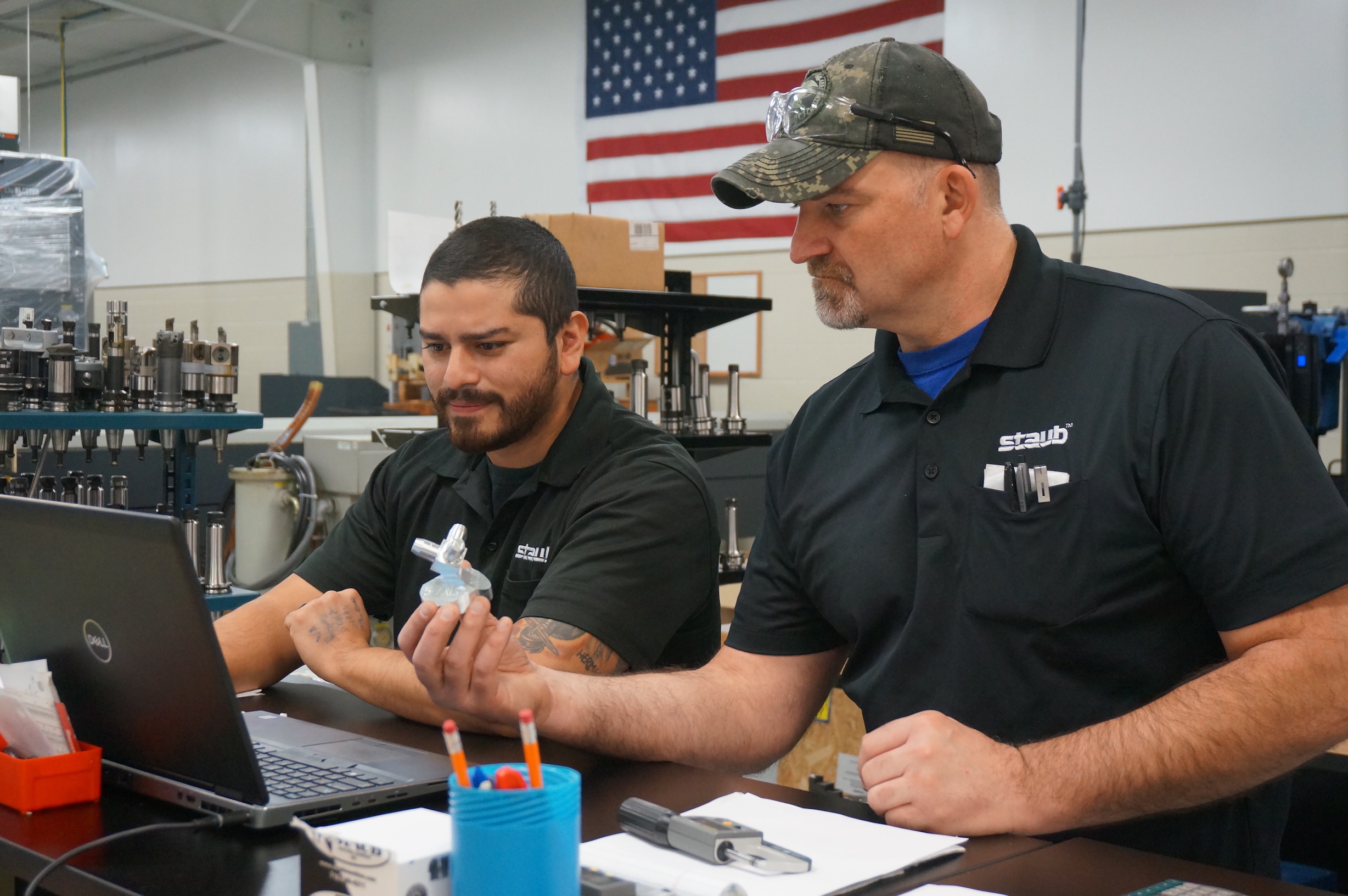
The Staub Difference: Tight Tolerance Machining
Staub Precision Machine is a shop that specializes in high-capacity precision machining. Our cutting-edge equipment achieves tight tolerances, and our automated process provides consistently superior quality. To learn more about our tight tolerance machining and other services, contact one of our friendly representatives today.
Last updated on June 9th, 2025 at 02:33 pm